www.vintagemodelairplane.com

Rover SD1 Efi System - (Flapper) Air Flow Meter

Description, Testing and Internal Adjustment

Part 2 of 2

NOTE: Contrary to erroneous instructions found on some recommended popular sites, the toothed wheel must be rotated in an anti-clockwise direction to reduce tension on the spring thereby generating a richer mixture.

• With the AFM flap at rest this image shows the position of the potentiometer wiper arm contacts pointing towards “X”. Its obvious then, to reduce tension on the spring requires its fixed end “A”, at the toothed wheel, should follow the direction of point “B” on the armature as it rotates in an anti-clockwise direction under the influence of the moving flap.

Calibrated Adjustment (including reasons 3, 4 and 5 above)

• In a perfect world the adjustments described here should only be made by experts but such specialists are difficult to find locally and may well be too expensive given the vagaries of our Rover SD1 Efi System and its potential for error.

• Therefore any expensive expert HELP may well be compromised if adjustments are unsuccessful due to faults elsewhere in the system.

• Thus, any fear about opening the AFM can be mitigated if owners spend loads of money unnecessarily buying new components or so called expertise when an AFM problem might be resolved with minimum outlay or hire/loan of suitable equipment and a couple of hours of sensible research and careful adjustment.

• Having said that, the AFM is the primary controlling source of injection mixture information and if it is abused then the system has very little chance of accidentally correct adjustment.

• A commonly available CO meter is the “Gastester” made by Gunson as either a basic unit or a more advance system, both available on Ebay for a modest outlay.

• With the engine at operating temperature, preferably after a normal run, measure the CO content at idle.

• According to the workshop manual for the Rover SD1 Efi System, the expected CO content reading should be 1.0-2.0% at an idle speed of 800-850 rpm.

• Lean mixtures will cause the engine to run too hot and an over-rich mixture may lead to an MOT failure as well as possible complications of carbon deposits leading to a lumpy performance.

• If the reading is already close to the requirement use the Allen headed air bypass adjustment screw to trim it to the preferred value.

• If the reading is way off the recommended value then it will be necessary to reset the AFM spring tension.

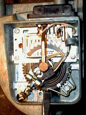
• Stop the engine, remove the AFM electrical connector and very carefully remove the cover as mentioned above. It is also possible to pry the cover off with a suitably wide lever between the thin end of the cover and the connector socket.

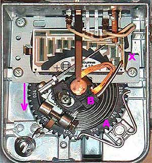
• Visually check the contacts on the potentiometer wiper arm point exactly to the lower left corner of the first rectangular resistor element seen to the left of “X” in the above image. If necessary adjust the position using the cross headed screw in the slot near the spindle

• This sets the correct start point for the potentiometer and the right position for operating the fuel pump contacts activated by the wire projecting from “B” to “X”

• Observe the toothed adjuster wheel that controls spring tension held in place by a “W” shaped wire retainer in two places.

• Replace the connector, start/warm-up the engine and adjust the plenum idle air screw to run the engine near the preferred idle speed of 800-850 rpm. The screw should be approximately half way between fully up and fully down; typically 4-5 turns out from fully home providing the idle air bypass gallery is completely clear

• Set the Allen headed air bypass screw approximately 2½ turns out from full home

• Mark the position of the wheel with a spot of paint or a knife cut.

• Only just loosen the bolt that secures the “W” shaped wire and hold the wheel firmly bearing in mind that it must not spin under the influence of the spring.

• Prevent the wheel from spinning under the influence of the spring and gently lift the ends of the “W” shaped wire to move the wheel one tooth at a time.

• Turn the wheel anti-clockwise to reduce spring tension and create a richer mixture across the whole engine speed range. Conversely, turn it clockwise to increase spring tension and create a leaner mixture. Watch the CO content reading.

• Aim to set the idle CO content at 1.5%, the mid point of the preferred setting for the Rover SD1 Efi system and use the air bypass adjustment screw to trim it to the desired reading. This will verify that both the wheel adjustment and the air bypass screw are having a controlling effect.

• Bear in mind there is a delay between making adjustments and the reading on the CO analyser and it is important to increase the engine speed to 2000 rpm every few minutes to clear out excess fuel condensed on the plenum chamber walls.

• Use the plenum chamber idle speed adjuster to maintain 800-850 rpm and go back to the CO adjustment screw to correct as required.

• Once satisfied with CO content reading the job is done.

• Before closing the cover carefully clean the resistive element with a cotton bud and alcohol and blow out any residue or dust with a low pressure air source.

• Reseal the cover to the meter using non corrosive silicone sealant as previously mentioned and let it cure overnight.

• Check and adjust the CO content after re-installation due to possible residual air transfer that may have occurred between the air flow (flapper) chambers and the unsealed potentiometer box.

• As a technical guide to CO content detection and analysis, accompanying this article is the “Gunson Gastester” Mk2 Handbook for further reading and research.

Conclusions

• The AFM is an important, intricate and expensive (as new) part of the system so there is an argument for not messing with its internals but seeking out expert help.

• Then again, experts can be rare, pricey and self-styled so why not obtain a low- cost spare S/H unit, study this article again in depth and give it a go? You Decide!

As a technical guide to Carbon Monoxide (CO) content, detection and analysis, accompanying this article is the “Gunson Gastester” Mk2 Handbook for further reading and research here (423kb)

Ramon Alban..............................................................................................www.vintagemodelairplane.com

Click here to return to Part 1

Or here to go back to Introduction Page

Please advise of errors and omissions.................................................Return to Efi Components Index

• The above image shows spring tension relaxed by five teeth. The original setting is marked with spot of paint.

• To reverse the procedure loosen the bolt, secure the wheel, lift the wire and rotate the gear wheel clockwise so the paint mark re-aligns to its original location.

• Use an exhaust gas analyzer to measure compliance with legal emission requirements. Idle CO adjustment is made by the Allen-headed screw.

• #: RTV382: Non-corrosive silicone sealant: http://www.intek-uk.com/rtv382.htm

• Mark the wheel where it is secured by the wire with a spot of paint or a knife mark that will not wear off.

• The wheel wiil try to spin under the influence of the spring so hold it firmly and just loosen the bolt securing the "W" shaped wire

• Lift the ends of the wire to rotate the wheel anti-clockwise five or six teeth, retighten the bolt and replace the cover.

• This creates a slightly richer mixture and turning the wheel clockwise    results in a leaner mixture. See NOTE below.

• This crude empirical process may require several attempts to get a desired result.

• Be sure not to damage the contact springs, potentiometer elements, or other delicate parts.

• TEMPERATURE..............K OHMS

• - 10°C ± 0.5°C.................8.26 to 10.56

• + 20°C ± 0.5°C................2.28 to 2.72

• + 50°C ± 0.5°C................0.76 to 0.91

• If readings are incorrect, substitute the AFM and recheck.

• If the readings are correct repeat the resistance check at the ECU harness plug pins 6 and 27 to verify continuity.

• If the readings are incorrect, check the red & brown wiring (RB) and the blue & red wiring (UR) and connections.

Initial Set-Up and Testing for CO content

• Obtain a calibrated exhaust gas analyser (or take the car to a garage who can perform the test) and operate it according to the manufacturer’s instructions.

• Be sure the air cleaner is fitted, there are no leaks in the exhaust system and that the probe is correctly positioned in the exhaust pipe.

• Check the CO content level at idle. If outside the limits specified (*), remove the tamperproof plug if fitted and adjust the mixture with the Allen headed screw fitted in the AFM. Turn the screw clockwise to richen the mixture and anticlockwise to lean it.

• (* Rover SD1 Vitesse & VDP Efi should be 1.0-2.0% CO content at 800-850 rpm.)

• When checking/setting CO level do not allow the engine to idle for longer than 3 mins otherwise give the engine a clear-out burst of 30 seconds at 2000 rpm, then re-check the CO. If necessary re-adjust the idle speed.

• If access to a CO meter is not possible, then the screw can be adjusted to 2½ turns out from fully home.

• For a working unit this will be an acceptable approximate setting and should allow the system to run normally. Fit new tamperproof plugs to complete the job.

• If at this stage a problem still exists with the AFM affecting engine performance then preliminary checks should be carefully carried out again before continuing.

Reasons for opening the Air Flow Meter

• Here are some reasons for opening up a Rover SD1 Efi AFM but owners must decide how prudent it is to proceed and what alternatives there might be to these suggestions. Either way, close study of the processes described will enlighten and inform the reader as to what is involved.

• 1) Inspect the instrument for suspected damage or contamination.

• 2) Crudely re-adjust spring tension in order to make an empirical change to the air/fuel mixture across the whole engine speed range.

•  3) Correct for age related relaxation of the internal spring. Such weakening of the tension results in a richer mixture, increased carbon deposits on the plugs and cylinder heads and excess CO emissions in the exhaust gasses.

• 4) Adjust the spring tension to take account of a changed engine capacity.

• 5) Make a calibrated adjustment to mixture control over the whole engine speed range using an exhaust gas analyser.

•  Before proceeding to adjust an AFM it is important to realise that there appears to be no readily available professional documents that specify a procedure.

• What follows is gleaned from reading the opinions of other amateur mechanics, various websites, workshop manuals, technician training manuals, my own interpretation of that information and, hopefully, a degree of common sense.

Crude Adjustment (including reasons 1 and 2 above)

• Carefully remove the cover using a sharp blade to cut away the glue sealing the cover to the body of the AFM.

• Inspect the internal components for obvious damage and blow out any loose contamination with a clean low pressure air source.

• If everything inside looks clean and tidy with no obvious signs of tampering such as witness marks on screws or additional paint dabs, marks or scratches, then it is very likely in good condition, so to keep the original settings, reseal the cover with a non corrosive silicone sealant such as RTV382, see note #.

• For individual owners who may not have access to professional adjustment equipment and techniques but never-the-less are willing to experiment, it is fairly easy to adjust the AFM to signal the ECU to (say) send in a little more fuel.

• This adjustment gives a slight increase in power and better throttle response. It does not seriously affect fuel economy but it can increase emissions. With care, it is a simple, reversible course of action.

• The flap is held shut by spring pressure so reducing its tension allows the flap to open farther for a given volume of air causing the AFM to signal the ECU for small increases in fuel compared to prior settings over the full engine speed range.

• With the cover off, observe the inside of the AFM. The “W”-shaped wire secured with a small bolt engages a toothed wheel and prevents it from turning.

• Conditions:

• Disconnect ECU multiplug.

• Ignition OFF.

• Remove air filter.

• Check temperature using suitable probe.

• Peel back rubber boot to gain access to terminals and connect ohmmeter to pins 6 & 27.

• Readings should be approximately as follows:

• If readings are incorrect peel back rubber boot covering connections at AFM.

• Repeat the tests at the AFM plug and then at the AFM socket.

• If readings are still incorrect substitute AFM.

• If OK, continue with next test.

Check resistance of Air Temperature Sensor.

• When performing this test, connect the ohmmeter for only a short period, as the meter battery (depending on the type of meter) may cause the sensor to heat up and give an incorrect reading.

• Conditions:

• ECU multiplug disconnected.

• Ignition OFF.

• Air flow meter flap closed.

• Connect ohmmeter to ECU multiplug terminals.

• Readings as follows.

• PINS OHMS

• 6 and 8 should be 360 ± 10

• 6 and 9 should be 560 ± 10

• 8 and 9 should be 200 ± 10

• (Note: Ohms, not KOhms).

Check internal resistance (ohms) of Air Flow Meter and wiring to ECU

My Vitesse at Speed

Home

About Me

Flying Faces

Crazy Rubberband

Vintage Freeflight Articles

Model Flying Tips'n'Tricks

Rover SD1 Tech'l Articles

Rover SD1 Efi Comp'nents

Rover SD1 Tech Manuals

Rover SD1 Tips'n'Tricks

Photo & Media Gallery

Site Contents & Map

Contact Me

My Family

Links


View My Stats

Problems with this site? Email Fatfingers Visit Sam35